| Moderated by: Greg Fletcher | ||
| Author | Post | |||||||||
|---|---|---|---|---|---|---|---|---|---|---|
|
Barthol Member
|
Hi Guys, After installing my 2,2 renovated engine i really understand why people says that stroking the engine is the single best thing to do to increase performance, Torque is dramatically imroved. My only problem is that it is smoking a lot during acceleration ( blue smoke) I received the bottom end of the engine rebuild and the cylinderhead also rebuild but not mounted. Looking down the cyl there was clear honing marks.( I do not know if the rings were changed) Cylinderhead looked good with a few new valves ( indicates t me that someone have gone through the troubles and checked the Clarences in the valve guides etc) There is no oil sealings on the valves,- is that even available for the 907 engine? Compression on all 4 cylinders is 190 psi just by using the starter to crank the engine and with throttles fully open. It starts , idles and runs very nicely , with only a little explosions from the exhaust on the overrun. Carbs are 45 dellortoes . I have taken of the inlet manifold to check the inlet valves and the stems looks nice and dry. Engine venting from the cranck housing is breathing ( it is connected to the airlifted box ) The vent from the valve cover is creating a little more vapor Any Ideas on where to continue looking , I would hate to swap back the old 2.0 engina as the 2.2 is a real improvement in terms of performance. BR Kim |
|||||||||
|
gmgiltd Member
|
Hi Kim, Chances are that it will use oil for several thousand miles untill it is fully run in. Most modern engines don't require the full regime and only advise you to avoid full throttle for the first five hundred miles or so. Stay off synthetic or semi synthetic oil for at least three thousand or the bores will never bed in. Take it easy for the first few hundred and gradually increase rpm and load over the next few thousand miles, trying to vary as much as practical. Once it's fully run in they still use more oil than modern engines most of the recent ones I have had don't use any between services - up to 20k in some cases. Gordon |
|||||||||
|
Barthol Member
|
Hi Gordon, I run it on Mineral oil 15/40. And the smoke is a lot, not in idle but during acceleration 2-3000 rpm . I have only done 200 km since the rebuild, so maby I should just continue to run it for some longer trips to see if the blue smoke clears :-) BR Kim |
|||||||||
|
Barthol Member
|
Hi Gordon, I run it on Mineral oil 15/40. And the smoke is a lot, not in idle but during acceleration 2-3000 rpm . I have only done 200 km since the rebuild, so maby I should just continue to run it for some longer trips to see if the blue smoke clears :-) BR Kim |
|||||||||
|
subwoofer Member
|
The "run it easy for two thousand miles" break-in routine is disputed, there is at least one other school of thought. Below is probably not the best reference, but it advocates the method I believe in. http://www.mototuneusa.com/break_in_secrets.htm I have also met train guys who say that when the diesel locomotives starts using oil the best thing to do is to load them hard for a day or two, that usually takes care of any glazing on cylinder walls. -- Joachim |
|||||||||
|
Barthol Member
|
Hi Joachim, Interesting reading. On my old Bikes I have used something in between. Running it through the gears, but gradually increasing RPM´s being very carefull to not let the engine pull from to low revs and keep changing the load on the engine. However never full throttle for the first 3-5 runs:-) I have purchased a USB endoscope and attached a Photo of cylinder 2. I clearly shows a little oil on the rear left side of the piston. Can this come from the piston rings / or from the valves? Is there a chance it will stop when the Rings have bedded in. Or should i take out the engine and physically check the rings. I have not mounted the pistons myself. Please consider that I have 190PSI compression pressure on all 4 cylinders:-) BR Kim Attachment: piston 2.jpg (Downloaded 168 times) |
|||||||||
|
gmgiltd Member
|
Hi Joachim, Loads of variables here petrol diesel air cooled or liquid cooled. Personally I would think that as the compression pressure is even at 190 then the rings and valves are ok for an engine that has just been built, glazing should not be an issue as the bores were honed 300km ago. The main thing is getting it up to working temperature so that the clearances are correct. Gordon |
|||||||||
|
Bfitz241 Member 
|
just curious...what type of rings were installed? cast iron, chrome moly, anything "special"? I know this is a stretch, but would you be able to do a leak down test on your engine? Last edited on 03-21-2015 03:24 pm by Bfitz241 |
|||||||||
|
Bfitz241 Member
|
I think I'm going to side with gmgiltd, this engine only has about 120 miles on it....but if it continues |
|||||||||
|
Barthol Member
|
Found the error. I ran the engine for a little while closed the throttle and just rolled to a stop in 2 gear,then immediately removed the inlet manifold. I found oil on the inlet valves in 2 cylinders.( a nice little amount) I guess that the engine goes out again for a cylinder head job. Is it possible to install oil sealings on the stems / guides? br kim |
|||||||||
|
Jensen Healey Super Moderator 
|
I have seen valve guides with seals from various sources. http://www.ebay.com.sg/itm/Lotus-Sunbeam-Esprit-Excel-Elite-Eclat-Bronze-valve-guides-stem-seals-/271054537358 The engine oil should be 20-50. This should help a bit until the head work can be done. Kurt |
|||||||||
|
Esprit2 Member
|
The 907 is not supposed to have valve guide seals. The engine is designed for high rpm operation, and that requires adequate lubrication for the valves. If the guides are worn, installing seals might stop the smoking, but it also gives up the lubrication the valves need. If you're going to granny drive it to get groceries, go with the seals. If you wish to drive it as it was intended to be driven, fix the root cause problem... the valve guides and/or the valves (worn stems). 190 psi compression pressure is very good, so I suspect the rings and valve seats are sealing very well. Jensen-Healey specified checking the compression cold, and Lotus specified hot. For the same engine, hot produces higher pressure readings than cold does. 8.4:1 cr = 7.58 - 8.96 bar (110 - 130 psi) COLD = Jensen-Healey spec 8.4:1 cr = 10.2 - 11.6 bar (150 - 170 psi) HOT = Lotus spec 9.5:1 cr = 11.2 - 12.6 bar (165 - 185 psi) Hot 9.44:1 cr = 11.2 - 12.6 bar (165 - 185 psi) Hot 10.9:1 cr = 11.5 - 13.0 bar (170 - 190 psi) Hot Are the cylinder liners iron or Nikasil coated aluminum? The 190 psi implies the engine is a 1985-92 912HC, which is a Nikasil liner engine. If so, then the 10.9:1 compression, 180 Hp, and 166 Lbs-ft of torque would be a nice bump over the stock J-H 907. Regards, Tim Engel Last edited on 03-23-2015 03:35 pm by Esprit2 |
|||||||||
|
Barthol Member
|
Hej Tim, Engine is supposed to be a 1979 907 standard engine with the standard liners( they are iron- magnetic) / pistons, Liners is honed but I do not know weather the rings have been changed. Crankshaft and rods are coming from a Bedford of some kind? I meassured compression ratio to 9,5:1. Cams are something similar to 107/104 ( Reprofiled cams) I measured my compression Cold by screwing the manometer into the plug hole, opening the throttle fully and crank the engine using the starter, until the reading stops increasing. I think I will change the oil to a 20/50 mineral before i take out the engine. |
|||||||||
|
Barthol Member
|
Hi Tim, Just forgot, The car is NOT for Granny Driving. In my opinion also old motors is supposed to be used as intended. It will definitely see the red line once it has proven that it is dureble. "Cars are for Driving" BR Kim |
|||||||||
|
Esprit2 Member
|
Good, they're more fun above 4500 rpm anyway. The 104/107 cam combination is the same as was used in the 912 HC. I've not driven that combination, but I have twin 104 cams in one otherwise pretty stock 907, and twin Dave Smith DS2 cams in a hotrod 2.2 907, and both will happily scream right past redline. If the internals are built for it, the cams will pull 8000 rpm. The 107 cam... not so much. But the exhaust cam is less of a factor in determining the engine's personality, and the 104/107 combination is still pretty sporty. Do you know if the Bedford crank is cross-drilled? The non cross-drilled crank isn't prone to running bearings at first flog. But the cross-drilled crank with the bearing shells that go with it are more durable if you're going to be using it's capability regularly. My 2.2 has a cross-drilled crank, but my two 2.0s are non cross drilled. Lotus Elite, Eclat & Excel (LC) were considered more civilized, and got non cross drilled cranks. The Esprit S1-S2, the Excel SE, and Turbo 910 were considered more boy-racer, and got cross-drilled cranks. The 190 psi 'COLD' is high for 9.5:1. Lotus specified 190 psi 'HOT' for the 10.9:1 CR... but don't complain, higher is better. If the cylinder head has been skim cut for flatness (.020" max allowed for the 907), the result would have been about a half a point increase in compression ratio (9.5:1 becomes 10.0:1). On the other hand, the modern composite head gasket's crushed thickness is about 0.020" more than the original gasket, so it lowers the compression by a similar amount. Tim Last edited on 03-22-2015 06:27 am by Esprit2 |
|||||||||
|
Barthol Member
|
I have no idea on how the bottom end is built . It was done from the Guy in Uk from who I bought the engine :-( How do I tell whether the Crank is cross drilled and have the right bearings, is it easy to see if I open it up any way ? If I pull the engine out again and need to install my old engine I need to sort an issue with the belt tightening wheel . The bolt is pulling a little to the left when I tighten the belt. The thread in the engine block is not so good. I have a semi automatic tightener but I cannot find out how to mount it. It looks like I am missing threaded hole in the engine. Is there anyone who have som photos / schematics showing how it is mounted. ? BR Kim |
|||||||||
|
Esprit2 Member
|
Barthol wrote: I have no idea on how the bottom end is built. It was done from the Guy in Uk from who I bought the engine :-(Can you get back to the guy you bought the engine from and ask about the crank & bearings? Pulling the cylinder head for a rebuild has nothing to do with the bottom end. Deciding to tear it apart just to check whether the crank is cross-drilled or not is totally unrelated, and optional. A non cross-drilled crank is not a fatal flaw, and is not necessary for an engine that is street-driven in a way that doesn't result in you knowing every judge on a first name basis. True, if you plan to flog it hard as a part of your daily driving style, then a cross-drilled crank and the lower bearing shells that go with it would be better. If the engine had individual main bearing caps, like most engines, then you could simply drop the sump, pull one cap, and take a look. However, the 9XX engines use one large Main Bearing Panel that captures all the journals at once. Removing it pretty much requires disassembling the bottom end. From what you have described, I don't think it's worth your effort. Instead, ask the guy who built it. "IF" you do tear it down for a look, then journals 1, 2, 4 & 5 of a cross-drilled crank will have two holes in the journal, 180 degrees apart. They are the opposite ends of the one drilling that passes all the way through... you can slip a slender rod (screw driver) through it. A non cross-drilled crank will have only one hole in those same journals. It's drilled at an angle to the rod journal. The lower bearing shells are for a cross-drilled crank are plain. No oil hole. No oil distribution groove. That's the point of cross-drilling. It allows the surface area of the lower bearing shell to be maximized to support the piston & rod's downward thrust forces by not giving up area to oil distribution. Then the cross-drilled passage in the crank takes care of distributing the oil. For a non cross-drilled crank, the lower bearing shells all have a central groove to distribute oil. It does it's job well, but takes away some surface area that would otherwise be available for supporting piston & rod thrust loads. In all 907s, the upper bearing shells have both a groove and a hole. 907 with NON cross-drilled crank Upper: Groove/Hole - Groove/Hole - Groove/Hole - Groove/Hole - Groove/Hole Lower: Groove/Hole - Groove/Hole - Groove/Hole - Groove/Hole - Groove/Hole 907 with cross-drilled Crank Upper: Groove/Hole - Groove/Hole - Groove/Hole - Groove/Hole - Groove/Hole Lower: Plain ............. Plain ............. Plain ............ Plain ............ Plain 912 with NON cross-drilled crank Upper: Groove/Hole - Groove/Hole - Plain/ Hole - Groove/Hole - Groove/Hole Lower: Groove/Hole - Groove/Hole - Plain ........ - Groove/Hole - Groove/Hole 912 & 910 Turbo with cross-drilled crank Upper: Groove/Hole - Groove/Hole - Plain/ Hole - Groove/Hole - Groove/Hole Lower: Plain ............. Plain ............. Plain ............ Plain ............ Plain Regards, Tim Engel |
|||||||||
|
Esprit2 Member
|
Barthol wrote:If I pull the engine out again and need to install my old engine I need to sort an issue with the belt tightening wheel. The bolt is pulling a little to the left when I tighten the belt. The thread in the engine block is not so good.It doesn't take long for a credible machine shop to rebuild the head (new valve guides... maybe new valves). You'll need to allow a week for new parts shipping, and the shop may have a job waiting list. The parts shipping time will probably fit into the waiting list time. If you pull the head, get it rebuilt, and put it back on, the engine will not be out of service long enough to justify re-installing the old engine. Don't bother. Just pick one path, and git 'er done. Regards, Tim Engel Last edited on 03-22-2015 09:26 pm by Esprit2 |
|||||||||
|
Jensenman Member
|
Barthol wrote:Found the error. This sounds to me like the valve stem to guide clearance is excessive, i.e. it needs new guides and possibly some valves. I would not recommend using valve stem seals, the 'bucket' tappet setup already restricts oil to the valve stems. Also, is there any reason not to rebuild the head from the original engine? Have that head reworked then spend a Sunday afternoon swapping heads. Well, since you'll need to adjust the valves make that a Saturday and Sunday. Last edited on 03-22-2015 09:39 pm by Jensenman |
|||||||||
|
Esprit2 Member
|
Barthol wrote:(Snip)... I need to sort an issue with the belt tightening wheel . The bolt is pulling a little to the left when I tighten the belt. The thread in the engine block is not so good.It sounds like you're talking about an eccentric tensioner here. All later J-H Mk II 907s, and all Lotus 9XX engines with eccentric tensioners use a stuc to mount the eccentric. I've not worked on a J-H Mk I (rope seal) 907, but my J-H parts manual calls out a stud and nut for mounting the eccentric. Does your engine actually have a bolt, or was that a casual mis-use of the term? In general, it's a bad idea to use bolt for a high stress, repetitive application in an aluminum part. The soft aluminum threads will take the brunt of the abuse, and wear or strip in time. A better solution is a stud, since for most applications, it's a one-time installation. Then the repetitive wear part of the assembly is taken by the studs steel threads, and little wear takes place. If the 'bolt' can wobble about, then it sounds like the threads require a repair insert. In that case, a threaded barrel insert (like a Time-Sert) is superior to a more common Heli-Coil. The stud needs to be perpendicular to the block's front face, and drilling the hole to accept an insert is not a good job for a hand-held drill. Taking the block to a machine shop to have the threads properly inserted will require a complete tear-down. As an alternative (it's worth a try), apply Blue Loctite 242 to the threads in the hole and on the 'stud'. Screw the stud into place and torque it to 20-25 Lbs-ft. Wipe off any Loctite that oozes out. Lightly wipe the eccentric with oil (especially it's bore) so that any Loctite residue you miss will not stick to it. Install the eccentric and tighten it's nut to 30 Lbs-ft. Allow it to sit undisturbed for 24 hours for the Loctite to fully cure. The tension should pull the stud up square to the surface, and the Loctite should hold it in position. Remove the eccentric, then go about fully installing the timing belt. Regards, Tim Engel Last edited on 03-22-2015 09:49 pm by Esprit2 |
|||||||||
|
Esprit2 Member
|
Barthol wrote:(Snip)... I have a semi automatic tightener but I cannot find out how to mount it. It looks like I am missing threaded hole in the engine. Is there anyone who have some photos / schematics showing how it is mounted. ?See the attachment. It doesn't show the block mounting hole details, but it does illustrate the general arrangement. Yes, you do need two threaded bolt holes in the block. And since all J-H 907s are 'early' 907s, and none used the spring-loaded, semi-automatic tensioner, it's possible your engine won't have the second bolt hole. In Lotus applications, there's usually something between the semi-automatic tensioner and the cylinder block. It may be an A/C compressor mounting bracket, or a belt snubber with short spacers on later engines, but something. On an engine with no accessory brackets, there will at least need to be a pair of longer sleeve-spacers to move the tensioner out to the plane of the timing belt. Examples of those parts are illustrated on the attachment, along with Lotus part numbers (probably no longer available from the factory). I suggest you contact Lotusbits and ask for whatever parts you need to complete the installation of your tensioner to a J-H 907 with no accessory brackets or snubbers. http://www.lotusbits.com/ *~*~* There were several versions of the semi-automatic tensioner as it evolved over time. The early one had a spring loaded metal piston moving in the aluminum housing's bore. It would gall over time, and seize. Later tensioners have a Nylatron plastic piston that solves the galling problem, and it will fit the early tensioner. However, if the bore is already galled, the damage is done and the plastic piston isn't any help. It needs a smooth, close-fitting bore. In early versions, the body's central hinge was just a steel pin in bored aluminum holes. If the holes wore, the moving part of the tensioner could cock at an angle, and the belt would tend to run off center on the pulleys. The official fix was to replace the tensioner. The later tensioner added Nylon bushings (shown in the attachment) to over-size hinge bores. If the bushings wear, just replace them and put the tensioner back in service. Make certain there is no slop in the hinge that will allow the roller arm to cock off to either side. Regards, Tim Engel Item .. Description .............................. Part Number 040 ... Snubber .................................. B907E1140F 041 ... Spacer, With Snubber ............... A907E1139F 042 ... Spacer, to block without Snubber A907E1138F 043 ... Stud. M10 ................................ B907E0504K 046 ... Bolt, M10 x 70 .......................... A075W2058Z Attachment: Timing Belt, Pulleys & Automatic Tensioner & Snubber - 1980-87 Esprit.jpg (Downloaded 178 times) Last edited on 04-25-2015 03:54 pm by Esprit2 |
|||||||||
|
Barthol Member
|
Hi All You are right , I do not think I can repair the Stud with the Engine in the car. As I have both Treads for the Semi automatic tensioner I think all I have to do is to make up a 1"" plate to get the correct distance. I thought about changing the head But the head in the cat has the larger inlet Channels, and I doubt it will be possible to exchange the head , shimming it etc with the engine in the car. I will fix the tensioner and change the oil to 20/50 mineral. If it continues to burn excessive oil I will pull it and do all the work in the bench. The old 2 ltr will then have to go back for this season :-) Thanks a lot for all of your inputs . BR Kim |
|||||||||
|
Esprit2 Member
|
Here's an illustration showing the A/C compressor mounting brackets. Note the two welded-in bosses surrounding the bolt holes in the upper right of the bracket. The timing belt's semi-automatic tensioner mounts through those holes, and the bosses space it out to the plane of the timing belt. Without that bracket in place, some other form of spacer is required for the tensioner. Regards, Tim Engel Attachment: AC Compressor Brackets - 1978-80 Esprit.jpg (Downloaded 179 times) Last edited on 03-23-2015 08:16 pm by Esprit2 |
|||||||||
|
Esprit2 Member
|
Notice the front main seal housing on the left is for use with the early eccentric tensioner, and is similar to the J-H unit. The later one on the right is for use with the semi-automatic tensioner, and with the eccentric tensioner as used on later engines. Note that the early/ left one has a eccentric tensioner boss cast into it's top edge. I've not attempted to use an auto tensioner with that seal housing, and don't know if it will work as is; but it would be a simple cut to remove it. You have both the early seal housing and the auto tensioner, so check out the fit and let us know what you figure out. Regards, Tim Engel Attachment: Front Main Seal Housing - 1974-80 907.jpg (Downloaded 178 times) Last edited on 03-23-2015 07:45 pm by Esprit2 |
|||||||||
|
Jensenman Member
|
I have a drill guide which I bought when a cylinder head bolt broke while disassembling an Isuzu Trooper V6. It was definitely accurate enough to center the bit in the broken off piece of head bolt. You'd have to remove the radiator etc for clearance but I bet it would work. I think this one is plastic; you'd want to get a metal one. 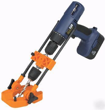 Last edited on 03-23-2015 09:13 pm by Jensenman |
|||||||||
|
Esprit2 Member
|
Review message #21. I've substituted a different JPEG attachment which illustrates a typical T-belt snubber (Aux Pulley location), the short spacers used with it, and the long spacers used to install the auto tensioner directly to the block. I think that's more relevant to what you're trying to do. Unfortunately, parts that old are probably no longer available from Lotus, but you might score some from Lotusbits. Regards, Tim Engel Last edited on 03-23-2015 09:29 pm by Esprit2 |
|||||||||
|
Esprit2 Member
|
Illustrations end up pretty lo-res by the time they're uploaded to JHPS. You can download clearer versions from my Dropbox account, here: https://www.dropbox.com/sh/kwl3ckub3in3wrm/AAA3CRJImDKvpslh-ySyQ_sza?dl=0 They're not large, hi-res files, but they're more legible than what shows up in a post. Browse the Dropbox, there's some other stuff in there that you may find interesting. Regards, Tim Engel Last edited on 03-23-2015 10:29 pm by Esprit2 |
|||||||||
|
Barthol Member
|
hi all Thanks for all the help . Esprit, that was a lot of valuable information:-) I Decided to change the tightener, which turned out to be a real good choice. The bolt on the old one was louse , and I could rock it around in the block until i could just pull it out. Guess this was a late save . There was some kind of thread insert but it had no threads left :-( BR 'Kim Attachment: JH bolt.jpg (Downloaded 157 times) |
|||||||||
|
Barthol Member
|
Hi, I have taken off the head ( engine out )and looking into the cylinders there is a big clearence between the cylinder and the piston. With the pistons in the middle of the bore i can actually move it from side to side ( inlet to exh) Using a dealer gauge shows me a clearance of 0,75 mm between the liner and the piston again with the piston in the middle of the stroke. I insert the gauge from the top and guess that i can reach down to the top piston ring. Is this the right way to measure the clearence between piston and liner? Looking in the manual it looks like the clearance is supposed to be between 0.0965 to 0,1219 mm. as previous I still measured compression of 190 psi whichh puzzles me , if the clearence is this big. Any Ideas ( It all started with a lot of blue smoke under acceleration, - however the engine performed very well) Br Kim |
|||||||||
|
Esprit2 Member
|
Barthol wrote:(Snip)... Using a dealer gauge shows me a clearance of 0,75 mm between the liner and the piston again with the piston in the middle of the stroke.Kim, The rings provide the compression seal, not the piston clearances with the liner. Excessive clearance will result in piston 'slap', which will result in excessive wear, and which can be heard. The piston is not a straight-sided cylinder, rather it has a slight taper (smaller at the top, larger at the bottom). As a result, the diameter must be measured at a specified position: Iron Liner ID - Grade A = 95.275 - 95.288 mm (3.7510 - 3.7515") J-H Grade B = 95.288 - 95.308 mm (3.7515 - 3.7520") Bore diameter is measured using a bore gauge, or T-pins and a micrometer, across the thrust axis, at 50mm down from top edge. Piston OD - Grade A = 95.1662 - 95.1789 mm (3.7467 - 3.7472") Grade B = 95.1789 - 95.1916 mm (3.7472 / 3.7477") Piston Diameter is measured with a micrometer, 90° to wrist pin, 15.0876 mm (0.594") up from skirt's bottom edge. Take both measurements above, then subtract to determine the clearance. Piston/ Liner Clearance = 0.0965 - 0.1219 mm (0.0038 - 0.0048") J-H. ..................................... 0.1016 - 0.1270 mm (0.004 - 0.005") Lotus. Same pistons, different corporate specs (Lotus rounded up the inch dimension). The 'observed' clearance at the top of the piston will be larger, as you have noted. Last edited on 03-30-2015 07:13 pm by Esprit2 |
|||||||||
|
Barthol Member
|
Hi again, Just measured my valve stems and the "side to side " movement of the valve at 10 mm open ( using a dial gauge ) I then recalculated the Measurement to STEM / GUIDE clearences I got the below tolerances measured in 1/100 mm and they all looks to be more than double of the max allowed 4,5 1/100 mm Will this be the reason of my engine burning oil and covering my surroundings in blue smoke during acceleration? When I send it out for reconditioning should I then go for the smallest possible tolerance between the guide and stem ? inlet EXH valve stem tolerence kalk tolerence stem tolerence kalk tolerence 1 7,130 11,000 4,890 7,100 25,000 11,113 2 7,130 40,000 17,780 7,105 22,000 9,779 3 7,135 20,000 8,890 7,130 25,000 11,113 4 7,125 20,000 8,890 7,100 22,000 9,779 5 7,135 10,000 4,445 7,110 30,000 13,335 6 7,135 25,000 11,113 7,130 20,000 8,890 7 7,135 20,000 8,890 7,125 27,000 12,002 8 7,130 28,000 12,446 7,110 26,000 11,557 stem dia 7,137 stem in mm play min 0,800 clearense in 1/100 mm play max 4,000 tolerence measured by checking wobble at 10 mm open then recalculted to stem BR Kim |
|||||||||
|
Esprit2 Member
|
Barthol wrote:(Snip)... I got the below tolerances measured in 1/100 mm and they all looks to be more than double of the max allowed 4,5 1/100 mmKim, Sorry, but I didn't follow everything you wrote; however "more than double of the max allowed 4,5 1/100mm" is a pretty clear statement. If your current valve stem to guide clearances are twice the max allowed, then yes that could explain why the engine is burning oil. And yes, when you have the valve guides re-done, shoot for the minimum side of the tolearance range. The clearances will tend to open up with wear, so new guide clearances should be closer to the minimum in order to optimise the service life before the clearances exceed the maximum limit again. Here are the valve stem clearance specs: Valve Stem Outsid Diameter - Intake & Exhaust 7.125-7.137mm (0.2805-0.2810") Valve Stem Clearance in Guide - Intake & Exhaust 0.008-0.046mm (0.0003-0.0018") Valve Guide Inside Diameter - Intake & Exhaust (ream to size 'after' fitting into the head) 7.145-7.170mm (0.2813-0.2823") Valve Guide Length - Intake & Exhaust 53.34mm (2.100") Regards, Tim Engel |
|||||||||
|
Jensenman Member
|
Valve stem excessive clearance will cause serious smoke this way: on deceleration in gear the throttles are closed which increases manifold vacuum. If there's any excess clearance at the valve stem, oil will get sucked between the stem and the guide. When the throttle is opened again, blue smoke. On cast iron valve guides, the clearances need to be as close to minimum as possible. Bronze guides will need a bit more because they are prone to seizing. Since the 907 has cast iron guides and doesn't use valve stem seals in the first place, as Tim Engel says the stem to guide clearance should be minimal. |
|||||||||
|
Barthol Member
|
Hi If I run the car at a constant speed of 50 MPH there is no smoke. Then If I floor it the car accelerates but sth blue smoke is a lot ( really a lot) and it continues as long as I run with full throttle. On the overrun with closed throttle there is no smoke. I have come to the conclussion that it must be related to at least the oil rings, maybe even the liner/piston clearence which is at max on 3 cylinders . As new pistons is quite expensive I will tru changing the piston rings and the oil scraper ring ( being very carefull to achieve the minimum ring end gap. If that does not help I will unfortunately be looking on a 7-800 GBP repair. new pistons/liners and rings:-( BR Kim Last edited on 04-25-2015 01:45 pm by Barthol |
|||||||||
|
Esprit2 Member
|
Kim, 'What you describe' indicates the rings are the cause of your smoke problem. If you disassemble the engine again, then take advantage of the opportunity to check everything, including the valve stem to guide clearances. Removing and rebuilding the engine is too much work to do it over and over, always going in with your blinders on and looking for just one thing. If you open the engine, then check everything. Last edited on 04-25-2015 03:59 pm by Esprit2 |
|||||||||
|
Esprit2 Member
|
The rings should not be gapped to a 'minimum', and there's such a thing as too tight. Each type of ring will have a specified gap 'range', so follow the manufacturer's instructions and make certain the gaps are within that range. The engine is 40+ years old, so it's likely the rings you get from a J-H or Lotus specialist will be aftermarket alternatives, and not factory OEM rings. 'IF'the rings are anything other than factory OEM, then ignore the J-H manual and follow the installation instructions that come with the rings with regards to gap, side clearances, and ring orientation. Check the piston to liner clearance. The bore should have a pronounced 45 degree cross-hatch. The rings depend upon a good cross-hatch to wear-in and seal against the liner. If the cross-hatch is original and worn smooth, then the rings may take 'forever' to bed-in. Don't use synthetic oil in a freshly rebuilt engine. It's too slippery, and it will inhibit the rings' ability to bed-in. Use a mineral oil during the break-in period, then (if you wish) switch to a synthetic at a later date. Last edited on 04-25-2015 06:02 pm by Esprit2 |
|||||||||
|
Barthol Member
|
I have opened the engine, and unfortunately the piston to liner clearence is app 0,2 mm which according to the manual is to much. The liners still have the Honing marks( guess that the guy I bought it from did that) I defenitely meassures to big a ring gap at the moment , but new rings will as you say be gapped according to the spec received with the rings. I am reluctant to replace the piston / liners as this is very expensive :-( How important for the sealing is the Piston to liner wear? Is it not the rings which are doing the sealing ( scraping down the oil.? Any idea on where to get the pistons if I have to buy new ones, and what types.? BR kim |
|||||||||
|
Esprit2 Member
|
Barthol, The liner bore is to be measured at 50mm down from top, across the thrust axis Grade A = 3.7510 - 3.7515" (95.275 - 95.288 mm) Grade B = 3.7515 - 3.7520" (95.288 - 95.308 mm) The piston diameter is measured 15.0876 mm (.594") up from skirt's bottom edge, and 90° to the wrist pin bore: Grade A = 3.7467 / 3.7472" (95.1662 - 95.1789 mm) Grade B = 3.7472 / 3.7477" (95.1789 - 95.1916 mm) Piston/ liner clearance is obtained by subtracting the piston OD from the liner ID: Clearance = 0.004 / 0.005" (0.10 / 0.13 mm) You report your clearance is 0.00787" (0.2 mm), which is too much. *~*~* The rings' proper fit is primarily responsible for the compression and oil seal; and the piston/ liner clearances has little to do with that. However, the piston can't be allowed too much room to flop around, or it will result in piston slap and excessive wear to the piston & liner. Both proper ring fit and piston/ liner clearance are important, each for different reasons. It's not okay to discount the piston's loose fit because your first concern is ring sealing and stopping the excessive smoking due to oil getting past the rings. I suspect (just guessing) the liners were worn and the previous owner honed them enough to clean up the surface and produce a good cross-hatch pattern; but in the process the liner ID ended up oversize. What are the dimensions you measured for the piston ODs and liner IDs ? *~*~* OEM pistons & liners are no longer available from the factory, either Jensen or Lotus. Your only hopes for 'original' is to find a dealer/ specialist who is sitting on a set of NOS parts, or to buy good used liners. However, if the liners are worn oversize, they don't have to be replaced. Instead, purchase oversized pistons, and have the liners bored as required to produce the specified clearance fit. JE Pistons makes nice forged pistons for the 907 that are superior to the original cast pistons. They come with new rings and wrist pins, and can be ordered in several oversize diameters and several compression ratios. Pistons and liners should be match machined. Don't just order pistons 0.0315" (0.8 mm) oversize from one source, and have the liners bored oversize the same amount by a local shop, and expect the clearance to turn out correctly. At a minimum, order the pistons first. Then take both the pistons and the liners to a machine shop hand have them bore the liners as required to produce the correct clearance fit. Each piston and liner pair becomes a matched set with their clearance near the minimum end of the specified range (above). If you order JE Pistons from JAE in California, USA, then they work with a machine shop near them. Order oversize pistons, and ship you're old liners to them. They will bore the liners to fit the new pistons. For an additional fee, they will also gap the rings to fit. You receive matched piston, rings and liner sets that are ready to install. On your side of the pond, I 'presume' Garry Kemp in the UK provides a similar service. Targeting piston/ liner clearance at the minimum end of the specified range give the greatest allowance for future liner wear. If the clearance ends up at the top of the range, then very little liner wear will be required to result in the clearance going out of spec too large. |
|||||||||
|
Barthol Member
|
Hi Esprit, I measured the liners to be between 95,28- 95,32 pistons are measured to be between 95,10 - 95,13 as you can see the best clearance i have is 0,18 mm and the worst is 0,22mm I guess that there is no way around new pistons? the price of having the cylinders bored is easily 50GBP a pcs, so I guess that new liners is not much more expensive.. I think I will give Gerry Kemp a ring :-) BR Kim |
|||||||||
|
Esprit2 Member
|
New liners need to be fitted to the block as required to produce the correct 'nip'... the liner's exposure above the block deck. At the factory, they had a large number of liners available, and selectively fitted liners to each block to get the nip right. If you order new liners, you might get lucky, or you might not. If the new liner's nip isn't right then you'll have to lap it into the block, or replace it. If you're current liners fit the block correctly, it's my humble opinion that boring them to fit the new, oversize pistons is easier. But that's just me. |
|||||||||
|
Jensenman Member
|
Your description of the smoking problem does indicate a ring, rather than a valve guide, problem. I once disassembled a Ford 2.3 which had the same complaint, on that one it turned out whoever replaced the pistons and rings snipped the end off of the 'expander' for the oil ring. If that is done, the 'rails' won't seal correctly. If I recall correctly, somewhere along the line there were shims available to adjust the liner nip. None of the usual suppliers seem to list them, but there's a Waukesha industrial engine which shares the 3.75 bore size and liner shims are available for it. http://www.powermaxparts.com/DEMO/WA-265-A.html |
|||||||||
|
Esprit2 Member
|
I don't recall any liner shims, but then there were a few J-H parts that never made it to the Lotus world. But if the shims are available, I'm working on an engine that could use a little more 'nip'. A shim 'donut' would have to slide on over the iron liner's spigot (the part that slips into the seat/bore in the block). The spigot's OD is: 101.360 - 101.384 mm (3.99055 - 3.9915") OD. The shim's OD should be about equal to the liner body's OD, but I don't have a dimension for that, or a liner handy to measure. |
|||||||||
|
Esprit2 Member
|
I lied, I do have a liner handy and it's OD at the step/ seat is: 4.294" (109 mm). So a liner shim would need to be something like: ID: 4.000" (101.6 mm) -0.000" / +0.???" OD: 4.290" (109.0 mm -0.???" / +0.000" Just laser cut a few out of stainless shim stock. Last edited on 04-27-2015 10:13 pm by Esprit2 |
|||||||||
|
DonBurns Member
|
I was looking for an answer to another question and noticed this discussion about liner nip, so thought I would add this recent experience. The machine shop had my block on the grinder and I mentioned the specification to the liner nip. Of course when I came back to look at the progress I saw that they had decked the block and liners flat - no nip. This lead to an argument about the need for a nip but I held my ground and insisted they fix it. They ended up spending quite a few hours (they say) programing their NC mill to grind the block down from the liners by the required nip. (Well - actually .003, but at some point you just give up). So it sounds like shimming the liners up is the way people usually go, but is there any reason why milling the block down should be an issue? My question, since I see valve clearances were also discussed in this string - I have a 2.2 liter, 104 / 107 cam combination and 9.6 compression. Are the valve clearances the same for any cam? So .006 In / .011 Ex regardless of cam? Thanks- |
|||||||||
|
Esprit2 Member
|
DonBurns wrote:So it sounds like shimming the liners up is the way people usually go, but is there any reason why milling the block down should be an issue?Anything that reduces the distance between the crank and the cams (milling the head, decking the block, etc) introduces that same amount of extra slack into the timing belt. By definition the cams are timed with the crank at TDC, and the crank cannot be allowed to drift off TDC. So as the tensioner pulls the new slack out of the run of belt between the crank and the exhaust cam pulley, it must draw it up and over the cam pulleys. That turns both pulleys counter clockwise, retarding the timing. How much? It depends upon how much the parts were machined; but something less that a full tooth pitch, so you can't do anything about it with stock parts. Aftermarket adjustable pulleys would be required in order to zero in on perfect timing. IMHO, that's worth it for a racing engine, but not for the street. On the other hand, Lotus introduced the current composite head gasket in Jan 1993. It's compressed thickness is about 0.5mm / 0.020" thicker than the original steel-asbestos-steel gasket, so it lifts the head that much higher off the block deck. Besides 'advancing' the cams a bit, raising the head also increases the combustion chamber volume, and reduces the compression ratio by about half a point... 8.4:1 becomes 7.9:1. When the new gasket was introduced, Lotus revised the machining on all new 910 & 912 engines (the 907 was long out of production), cutting the block deck that much lower, and seating the liners a like amount deeper to preserve the Nip. So engines built since Jan '93 have the correct compression with the new gasket, and all older engines have 0.5:1 less compression that they started with. If you're ever faced with decking the block a few thousandths for whatever reason, consider taking the full 0.5mm / 0.020", just to get your compression back. Alternatively, if you ever buy new pistons, order half a point more compression that you really want. DonBurns wrote: I have a 2.2 liter, 104 / 107 cam combination and 9.6 compression. Are the valve clearances the same for any cam? So .006 In / .011 Ex regardless of cam?The 104 and 107 cams both use the same valve clearances: 0.005 - 0.007 Intake 0.010 - 0.012 Exhaust If you converted a 907 to 2.2 and are using the stock 907 head with the 104 & 107 cams, the stock valve springs will go coil bound due to the extra lift. The 910 & 912 heads are built from the start to work with the high lift cams. For a 907 head, there are special thin-wire springs available from Dave Bean Engineering, and probably some of the other USA Lotus specialists, like JAE. I don't know if Delta carries them; but they sell the cams, so they might have the springs to go with them. In the UK, it seems more common to machine the valve pockets in the head a little deeper to allow for the extra lift. Either method will work... just be sure that you do 'something' to allow for the lift. If you don't, something is going to break the instant you try to start the engine. Regards, Tim Engel |
|||||||||
|
DonBurns Member
|
Tim- Thanks for the feedback. I did fit the "competition valve springs" that are sold specifically for use with 104 and 107 cams. The club store mentions they are necessary to avoid valve float (bounce?) but no mention of the binding issue, but I have to assume the springs are correct - the engine did not break when started anyway. I also fitted "big valves" , 1.450" Intake and 1.275" exhaust, and the upgraded studs to allow the newer torque specs, and new JE 9.5:1 pistons. I wonder if the final compression of 9.6 is due to the decking work. I had not thought of the valve timing changing due to decking the block. I always thought decking was a standard part of any rebuild. When I have a moment I will do the math and calculate the degrees of cam shift that would go with the .1 compression increase. Although there are other factors going on, like CC'ing of the head and thicker head gasket, so I'll just calculate cam turn per mil. I have another concern at the moment. The builder did so many things wrong besides decking the liners flush (no thermostat, no oil in the transmission and several more minor issues) that now I'm wondering if they put the cams in the right place. I told them (but I told them about the nip as well) and the boxes were marked, but... Anyway I was going to check the lift yesterday and took off the intake cover and was setting up my dial gauge, but realized mine is only a .25 maximum gauge. I think that should work as a way to verify once I get the correct gauge. |
|||||||||
|
Esprit2 Member
|
DonBurns wrote:The club store mentions they are necessary to avoid valve float (bounce?) but no mention of the binding issue, but I have to assume the springs are correct.Hmmm... the stock valve springs will rev beyond the stock tappets' and rods' max rev limits, so I don't see higher as being an issue. But that's picking nits... the real point is that the upgraded valve springs are also necessary to avoid going coil bound-with the high lift cams. You've covered that base. DonBurns wrote: I wonder if the final compression of 9.6 is due to the decking work.It's like touching a spider web... everything affects everything. The compression ratio will vary with all those things, and I can't tell you from here what is dominating in your engine. If you really want to know, then CC the combustion chambers, and add the incremental volume of the thicker gasket. DonBurns wrote: now I'm wondering if they put the cams in the right place.Are the cam's "Lotus" OEM, or regrinds? Lotus marked the cam's exposed shank... the part visible between the back of the pulley and the front of the cam carrier/ seal. The 104 cam will have a string of 444444444...s stamped around the shank, and the 107 will have 7777777...s. If they're regrinds, then you're at the mercy of whomever reground them... did they re-mark the cams in any way? Usually not. Failing that, the lift is the easiest to measure identifying trait... you're on the right track. C-cam = No grove/ no marking. D-cam = One grove. E-cam = Two grooves cut around the shank. 104 cam = 444444444444.... 107 cam = 777777777777.... The part number cast into the camshaft is for the raw blank, not the ground cam. It's the same for all. Regards, Tim Engel Last edited on 01-16-2017 10:22 pm by Esprit2 |
|||||||||