| PM | Quote | Reply | Full Topic |
| Joined: | 07-16-2014 |
| Location: | |
| Posts: | 200 |
| Status: |
Offline
|
I have been temporarily defeated by the starter solenoid. At least, that's what I think has defeated me. Allow me to explain...
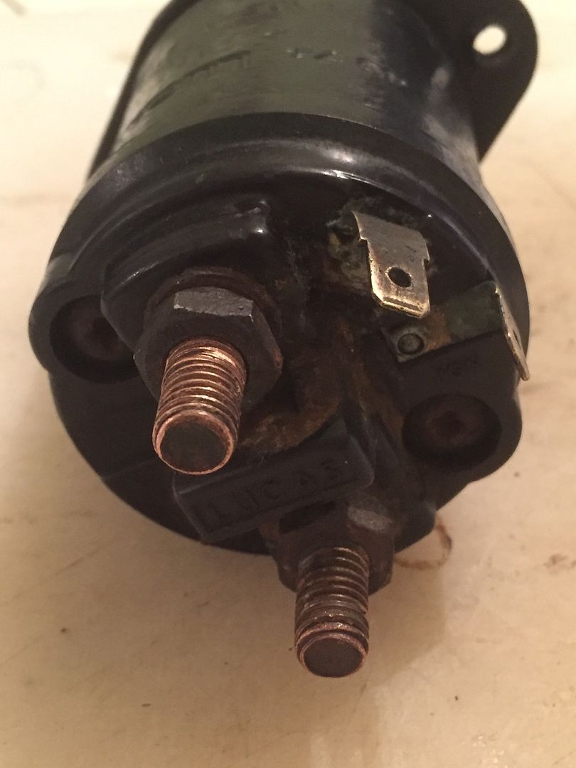
I fitted new headlight units, and relays yesterday. All went well, but note I took the +ve feed for the headlights off the +ve battery feed post terminal on the starter solenoid (on the left in the image below), which meant undoing the securing bolts so I could put the relay ring terminal on the terminal. The headlights work fine. But when I tried to start the engine to test the improvement in voltage loss in the headlight circuitry, nothing. No click, to whir of the starter motor, and certainly no cranking of the engine.
So I pulled the starter solenoid and tested it. No continuity between any of the terminals, apart from about an ohm between the -ve / starter motor post terminal (on the right in the image below) and the larger diagonal spade terminal (top left in the image below). It seems to me that there should be continuity between the +ve battery feed post terminal and the larger diagonal spade terminal, as the former provides the +ve feed to the coil resistor which retracts the solenoid piston when energised and the latter is the earth for this resistor coil?

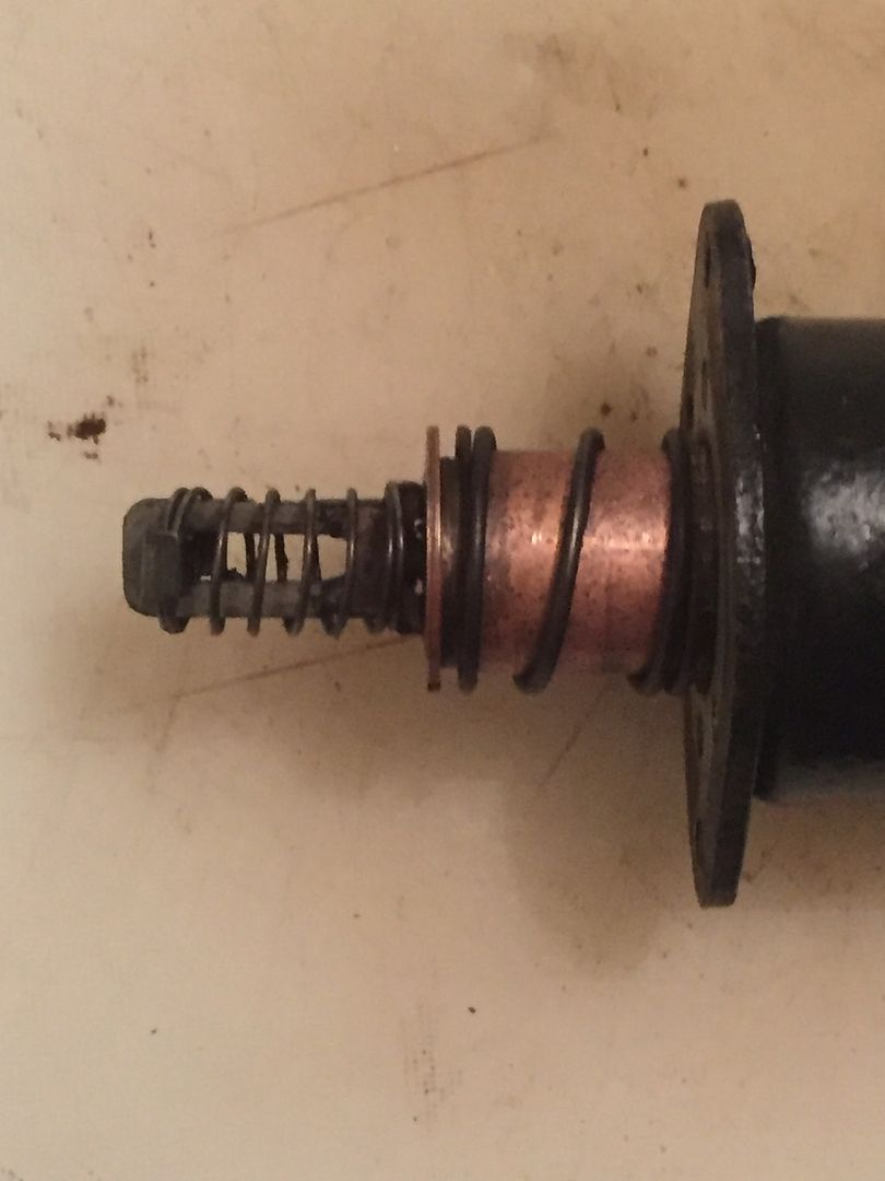
Getting the solenoid back onto the starter motor was a pig, I cannot see an easy way of retracting the spring so that the "eye" at the end can slide over the lever that points upwards in the solenoid housing and which presumably engages the starter motor crank with the flywheel when the solenoid is activated (see image below). Is there a knack to this?

I've tested all the other parts of the solenoid circuit - there is good voltage to the +ve battery feed post terminal, good earth at the -ve / starter motor post terminal, and 12.5V from the red-white wire coming from the ignition switch. But which of the spade terminal should this red-white wire attach to, the slightly smaller one marked "IGN" (top right in the image above, you can just about see the letters on the black solenoid cap) or the larger diagonal one? I can also make the starter motor turn by shorting between the two post terminals, so the starter motor itself is fine.
I've also managed to make the starter motor whir by turning the ignition, if the red-white wire is connected to the "IGN" spade terminal, but I don't think this is the correct connection, I think this spade terminal is for the yellow-white wire which provides 12V to the coil when cranking, for cars fitted with a ballast resistor.
I am at my wits end here. Does anyone have any idea re the various issues I've outlined?
Best wishes,
Nigel